Garrattfan's Modelrailroading Pages
AD60
3.1 Superstructure rear unit
|
Instructions [171]-[192], page 19 of the rewritten instruction manual |
|
The nice thing about the superstructure of this loco is that it can be built in separate parts parallel to the building of the frame. So when I got fed up with the fiddly work on the frame I started working simultaneously on the front or rear unit's superstructure to get some diversion. |
|
 |
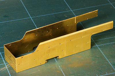
The rear bunker's sides and rear walls are provided in one etch, probably the nicest etched part the whole kit contains. The etch comes with the inset edges on the top already factory made.
[171] Work starts with deburring all sides |
[172] After folding. Just the very looks of it... |
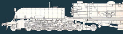
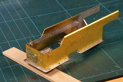
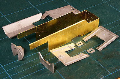
All major structural parts of the superstructure. |
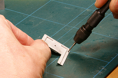
Again, in analogy to the front unit's superstructure, drill all holes. |
[174]-[177] Soldering the lifting links (straightforward 180C). |
 |
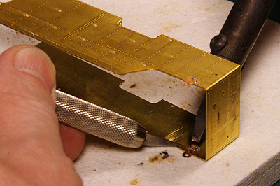
[178] Joining the etch and the front footplate with 80C solder. 80C solder does not bond to brass very well. So it is advisable to tin the edges of the etch with normal 180C or 140C solder before soldering with 80C |
 |
The rear footplate comes next as well as the hopper front plate.
Now some remarks on "rear" and "front". DJH do their best to make things utterly confusing. What is front and what is rear on a locomotive? Well, the front is where the front of the boiler points. So the outward end of the rear unit holds the rear footplate, because it points away from the boiler, right? Still DJH call it the front footplate, and consequently they call the other footplate (the one closest to the boiler) the rear footplate. Things get really confusing when instruction [181] says: Fix the hopper frontplate (103) to the rear footplate (102). Yeah....errrm, what? |
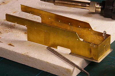
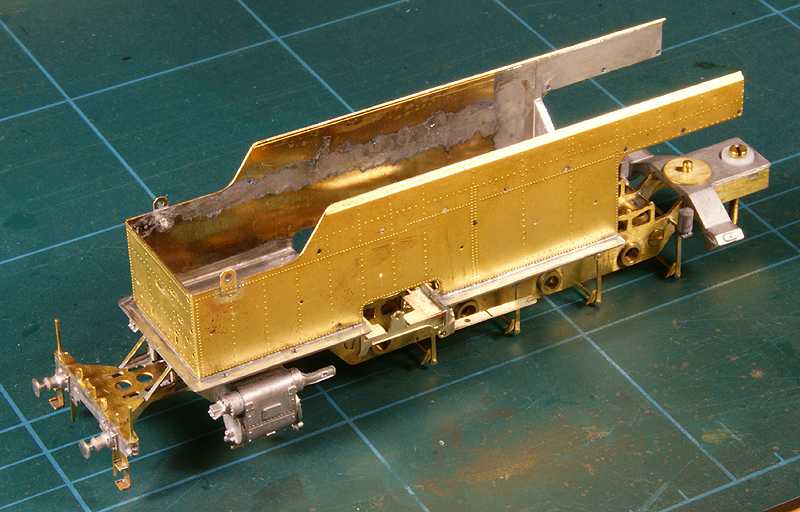
The assembly is offered up to the frame to trial fit. Note the tinned area that will later take up the deckplate and the handrail knobs. |
|
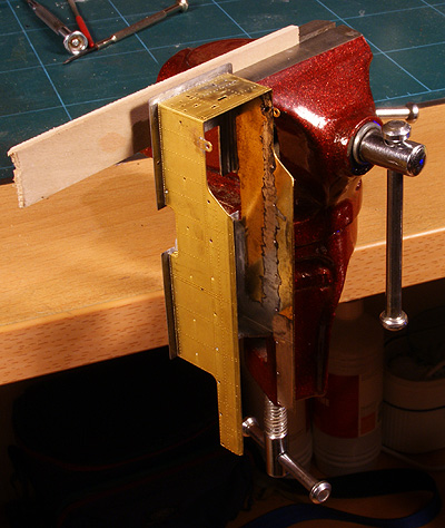 |
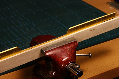
Handling the rear bunker is not always easy. I attached a piece of wood by drilling it and inserting a screw into the mounting thread. This way the bunker can be clamped in a vise, here to demonstrate the position when adding the many details on the rear, and .... |
 |
.. it is also more firmly on the ground for other work. |
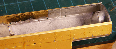 |
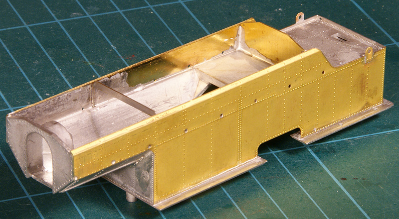
[187]-[190] The hopper door plate and the hopper floor in place |
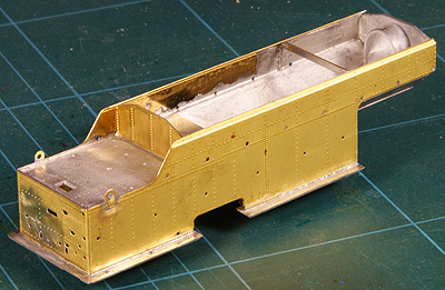 |
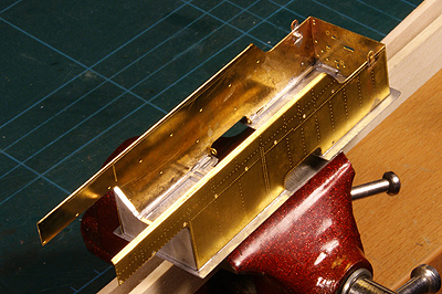
On this photo the hopper side support (111) is already in place as per [193]. I decided not to use the white metal casting that suggests a coal load. I will later add real coal in the hopper. |
The main structure of rear bunker completed. |
|

Sign my
GuestBook